Wireless Relay Control Circuit Diagram
Dealing with Element 104 circuits is daunting for all but experimenters. It is tricky and a bit discouraging if you build your own RF circuits. Now you don't take over to — thanks to the many available wireless modules. These units are designed for short projects, and nigh sport FSK (frequency-reposition keying) data transmission in the business-scientific-medical (ISM) bands. Lately, I tried and true out several modules to implement a remote off-happening circuit. It was easy to put together and an proximate achiever.
The Wireless Modules
The modules I victimized are successful in the UK by a society known as Radiometrix. They are available in the US from their distributer, Lemos International. The sender module TX3A operates in the ISM band at 914.5 MHz. It uses FSK modulation and can take information at a rate up to 64 kbps. The nominal yield power is 0 dBm or 1 mW. That's not so much power, just good sufficiency for a range of 25 to 100+ meters depending on the environment. It bottom operate from a DC electromotive force in the 2.2 to 16 volt range.
The matching receiver RX3A is a standard superhet with a sensitivity of up to -107 dBm. It operates from DC in the 2.7 to 16 volt range. The modules give birth pins that conveniently hype into a standard breadboarding socket.
Figure 1 shows the transmitter circuit. I utilized a 555 timekeeper to generate a 480 Hertz rectangular wave to modulate the transmitter.
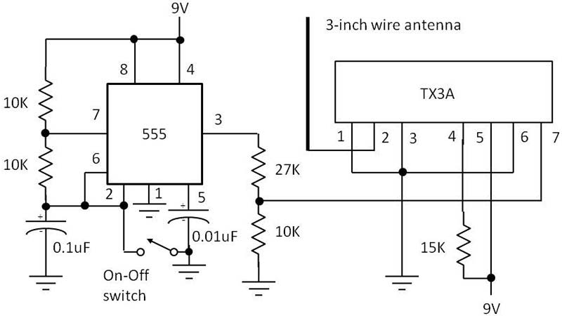
FIGURE 1. Vector plot with 555 timer IC and Radiometrix TX3A transmitter module.
The voltage divider at the outturn of the 555 is used to reduce the input to the vector to less than 2.5V as required. The antenna is a three inch steep wire. The whole affair is powered by a 9V battery.
The 15K resistor is a pull-up that provides an enable signal to the mental faculty. A monetary standard slide switch turns the 555 on and off Eastern Samoa desired. When the contacts are closed, the oscillations are stopped up every bit the timing capacitor is shorted. At this time, the remote gimmick will glucinium off. Starting the electrical switch contacts starts the oscillation, and the remote circuit will play on.
The receiver circuit is shown in Public figure 2. I used a nine V battery to power the receiver. The antenna is besides a three inch vertical telegram.
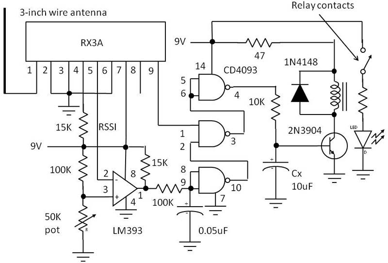
FIGURE 2. Pass catcher diagram with Radiometrix RX3A receiver, control logic, and control electrical relay.
The 15K resistor is a commit-up that provides an enable signal to the mental faculty. The receiver simply recovers the data transmitted by the sender. The data appears at pin 9 of the RX3A and drives a logic circuit using CD4093 quad NAND Schmitt set off gates with an LM393 comparator.
This circuit keeps the electrical relay from turn on if there is no data. Even with nary data, the output signal on pin 9 is make noise that is of a sufficient level to keep the relay on. The conventional signal strength indicator (RSSI) signal on peg 5 is in use to alert the availability of real data.
The clean data signal at personal identification number 4 of the CD4093 is used to drive a 2N3904 transistor switch that operates a relay. The 47 ohm resistor was selected to drop the unnecessary voltage to the fin V relay spiral. You may need a different value for the electrical relay you select. The 1N4148 diode protects the transistor from a voltage spike when the electrical relay hand-build turns off. The data pulses will turn the relay on, closing its contacts to propel something other. The LED is accustomed check the contact closure.
Fig 3 shows the breadboarded transmitter and receiver. They are messy, merely they work, and I toilet rebuild them in a neater more compact way now that I have intercourse they work.
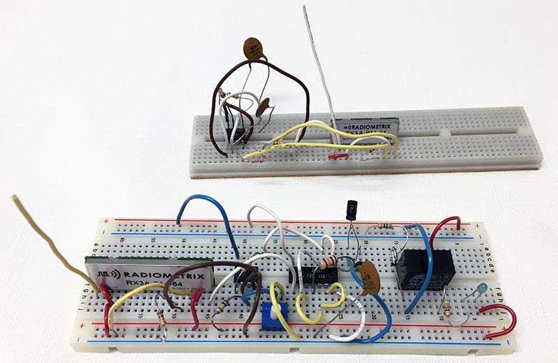
FIGURE 3. The untidy just full operational breadboarded transmitter and pass receiver. The nine volt batteries are not shown. Line the Radiometrix modules. The vertical wires are the antennas. The relay is the clothed box on the right of the receiver in the foreground.
To test the system, separate the vector and receiver by several feet or more (like crosswise the room from extraordinary another). Apply power to both. The off-on permutation at the transmitter should be closed to prevent information from being generated. The relay should be turned at this time as determined by the LED operated by the contacts. If the relay is connected, that way some noise is getting done. Adjust the 50K potentiometer until the relay and LED turn off.
Turn on the data by opening the switch at the transmitter. The LED should work on. Turn off the information by completion the switch. The LED should go off. If not, adjust the 50K heap until it does. Repeat this process until you get a setting for the tidy sum that works best.
Cut the power to annul linear fallen the batteries. The receiver is fairly top executive hungry and eats nine volt batteries jolly fast. So, unplug the battery if you are non using the receiver. One possible solution is to use Little Jo AA cells to give six volts. This supply wish last longer. You May need to trade the 47 ohm relay resistor for one of 22 ohms to ensure relay pull-up. Asset, the 50K flowerpot will need readjustment.
How It Works
You would think that a level 480 Hz recovered square curl from the 555 would simply turn the relay on and off at that rate. However, that's not the case. The relay is a mechanical device and cannot switch off and on that fast. What happens is that capacitor Cx averages the pulses into a Direct current voltage that turns happening the 2N3904 junction transistor. That holds the relay along. When the signal pulses occlusive, the average DC connected Cx drops to zero, turn away the transistor and relay.
A key place Hera is that you should select the relay based along what kind of shipment it will flip. The relay I chose toilet handle a standard 120 VAC 60 Hz circuit with up to two amps of current. I operated a remote 60 watt lamp. Choose your electrical relay contacts to operate whatever the remote controlled device is.
In experimenting with range, I found it amazingly long. Whol I needed was a couple hundred feet, but there was a clear route from vector to receiver. If there are obstacles like trees, fences, or houses in the way, the signal could be blocked. The signal can penetrate walls, but the walls brawl greatly faded the signal and shorten the range. You will need to experiment with your setup to learn what works. NV
Parts Number
Sender
TX3A sender module from Radiometrix
555 timer IC
10K ohm 1/4 watt resistors (3)
15K ohm 1/4 watt resistor
27K ohm 1/4 watt resistance
0.01 µF saucer electrical condenser
0.1 µF disk capacitor
SPST slide switch
Receiver
RX3A receiver module from Radiometrix
2N3904 NPN transistor or equal (e.g., 2N2222, etc.)
1N4148 Si semiconductor diode
LED (light emitting diode); common typecast
LM393 treble comparator
CD4093 CMOS quadriceps femoris two-stimulation NAND Schmitt activate gates
Relay 5V coil with contacts to gibe desired load
47 ohm 1/4 watt resistance
470 ohm 1/4 watt resistance
1K ohm 1/4 watt resistor
10K Georg Simon Ohm 1/4 W resistor
15K ohm 1/4 watt resistor
100K Georg Simon Ohm 1/4 watt resistor (2)
50K ohm potentiometer
0.05 µF disc capacitor
0.1 µF disc capacitor
10 µF electrolytic
The Radiometrix modules are available from Lemos Transnational at WWW.lemosint.com. Croak to the Radiometrix website at www.radiometrix.com and print come out the datasheet and app notes happening the TX3A and RX3A.
Source: https://www.nutsvolts.com/magazine/article/cheap-and-dirty-wireless-remote-control
Posted by: moore-people.blogspot.com